Diagrams
A diagram is a visual representation of a model. Diagrams are the bread and butter of UML, and, as such, the majority of the work when creating architectures in StarUML is spent creating diagrams.
Creating a Diagram
To create a diagram:
- Right-click on the element in the Model Explorer that you want to add the diagram to
- Hover over Add Diagram
- Select the type of diagram that you want to create from the sub-menu
- Double-click the name of the diagram in the Model Explorer
- In the Properties box, below the Model Explorer, update the name field to the desired name of your diagram
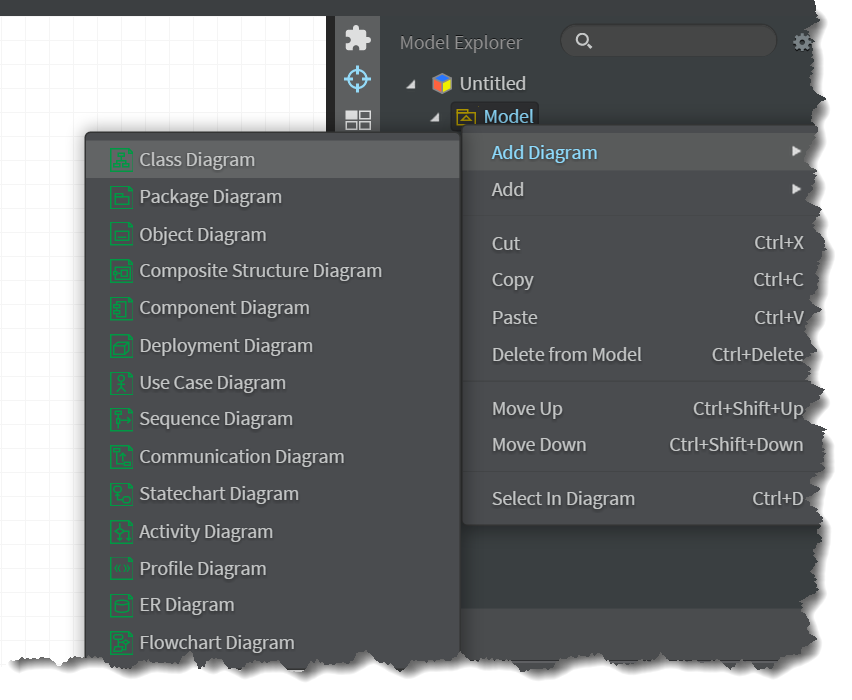
Diagram Sets
In SitecoreUML, all template architectures should include at least one set of two diagrams, a Templates Diagram and a Template Folders Diagram, living under a common Model element. Note that the diagram names are for description purposes, only; they are not types of diagrams. In actuality, the Templates Diagram is a Class Diagram and the Template Folders Diagram is a Package Diagram.
It is recommended that there be one Templates Diagram and one Template Folders Diagram per Model element. This is referred to as a Diagram Set. To clarify, SitecoreUML does not require that you structure your project into Diagram Sets in order to function properly. However, it is the recommended practice, as following the recommendation will help you to keep your project's diagrams easier to read and organized, to avoid relationship and manipulation issues that could corrupt your project, and to enforce the restriction that there can be at most one parent per template.

SitecoreUML allows for the creation of as many Diagram Sets for an architecture as desired. As will be discussed later, repeating folder paths will not create duplicate items when deploying. As such, the number of Diagram Sets in an architecture depends on the architect and the complexity of the architecture. When creating simpler architectures for smaller sites, I tend to avoid having multiple Diagram Sets, as it takes a bit more work to have them. In contrast, when working on larger or more complex architectures, I tend to create a separate Diagram Set per module. Having separate Diagram Sets per module also carries with it the advantage of helping to identify and avoid dependencies on templates in other modules during while creating the architecture.
Note that the architecture examples illustrated in the chapters of this book are simplified for easier consumption, and thus make use of only one Diagram Set. I intend to add examples of architectures with multiple Diagram Sets to the Samples section, in the coming weeks.
Note also that at present, SitecoreUML does not include options for deploying only one Diagram Set at a time. There is a feature task for adding support for deploying specific Diagram Sets added to the Project Roadmap.
Templates Diagrams
Perhaps the most visibly important component of a SitecoreUML architecture is the Templates Diagram.
The role of the Templates Diagram is to visualize all of the diagrams in the architecture. The vast majority of the editing and authoring of the templates in the architecture is performed directly in the Templates Diagram, as well.
As previously mentioned, Templates Diagrams are so named for labeling purposes and are actually required to be Class Diagrams. Considering Sitecore’s data model and the fact that most modern Sitecore solutions make use of an object-relational mapper (ORM), e.g. Glass.Mapper, to map Sitecore templates to class or interface models, it makes sense that our templates diagram would be a Class Diagram.
While SitecoreUML does not require your Templates Diagram to be a Class Diagram, it is the recommended practice.
Template Folders Diagrams
The Template Folders Diagram, serves as a visual representation of the template folder structure in the architecture.
For those new to UML, it is important to know that, when modeling with UML, folders and namespaces are represented by “Packages”. While a package may be added to any diagram, there is a type of diagram specifically meant for visualizing packages and package relationships, which is the aptly named “Package Diagram”. We will discuss "Packages" further in the Template Folders chapter.
As with the Templates Diagram, while SitecoreUML does not require your Templates Diagram to be a Class Diagram, it is the recommended practice. To that end, SitecoreUML actually does not require you to have a Template Folders Diagram at all. You could do everything in your Templates Diagram. However, this will complicate your Templates Diagram and make it increasingly difficult to read. Depending on the size and complexity of the solution, putting everything in one diagram may not be a viable option. It is for this reason - for sake of organization and clarity - that the SitecoreUML recommended practice is to abstract out the template folders into their own diagram.
Views
Recall from the last chapter, Projects, that Models are not Diagrams, and that diagrams are visualizations of a Model. Similarly, Views are visual representations of a model element; a symbol or other graphic that represents an entity of the model.
If a diagram is blank and has nothing on it, then there are no views on it. If a diagram has two elements connected by an arrow symbolizing a relationship, then there are three views on the diagram: one for each connected element, and one of the arrow that connects them.